PRODUCTS
This section offers an overview of the main standard products in our catalogue. For more specific requests, our technical office can propose customized solutions to ideally match your needs.
.
STRAIGHT STEPPED COLUMNS
 The straight stepped columns in the PR range produced by CML s.r.l. are supports designed and built to sustain one or more lamps or projectors.
The column is realized with cylindrical tube elements with decreasing diameter towards the upper part, appropriately fitted (stepped) and welded in sequence.
They are prepared for the assembly of:
– one column head lamp
– one series of fittings with pre-fixed inclination to gather from 1 to 4 lamps at the same time – single, double, triple arm brackets
– cross-members for mounting projectors.
The standard workings at the base of the column include: n° 1 slot for terminal board, n° 1 connection for the earth plant, n° 1 cable inlet slot.
The details of these standard workings performed at the base of the column are indicated separately in this catalogue on page 25.
MATERIALS:
TUBE: tube realized in S 235 JR (UNI EN 10025) sheet steel
produced with ERW type-approved procedure.
WELDING:
circumferential performed with IIS certified automatic procedure.
TREATMENTS:
hot galvanisation in compliance with UNI EN 1461 of all components painting with thermosetting polyester powder cycle for outdoors.
REFERENCE STANDARDS:
The columns are built in compliance with the UNI EN 40-5 Standard and the connected standards:
Dimensions and tolerance: UNI EN 40-2; Materials: UNI EN 40-5; specification for characteristic loads: UNI EN 40-3-1; Verification by calculation: UNI EN 40-3-3;The columns are “CE” marked in compliance with the EEC 89/106
Directive dated 21-12-1988.
“CE” MARK:
Application of adhesive “CE” plate onto every column.
TECHNICAL DOCUMENTATION:
Table of column performance elaborated in compliance with UNI EN 40-3-3, “CE” declaration of conformity for every supply batch.


STRAIGHT STEPPED COLUMNS (FOR LARGE AREAS)
 The straight stepped columns in the GA range produced by CML s.r.l. are supports designed and built to sustain one or more projectors. The column is realized with cylindrical tube elements with decreasing diameter towards the upper part, appropriately fitted (stepped) and welded in sequence.
The columns are realized from two coupled sections that must
be blocked using n°6 bolts.
They are prepared for the assembly of:
– cross-members for installation of projectors.
The standard workings at the base of the column include: n°
1 slot for terminal board, n° 1 connection for the earth plant,
n° 1 cable inlet slot. The details of these standard workings
performed at the base of the column are indicated separately in this catalogue on page 25.
MATERIALS:
TUBE: tube realized in S 235 JR (UNI EN 10025) sheet steel produced with ERW type-approved procedure.
WELDING:
circumferential performed with IIS certified automatic procedure.
TREATMENTS:
hot galvanisation in compliance with UNI EN 1461 of all components painting with thermosetting polyester powder cycle for outdoors.
REFERENCE STANDARDS:
the columns are built in compliance with the UNI EN 40-5 Standard and the connected Standards: Dimensions and tolerance: UNI EN 40-2; Materials: UNI EN 40-5; specification for characteristic loads: UNI EN 40-3-1; Verification
by calculation: UNI EN 40-3-3.
The columns are “CE” marked in compliance with the EEC 89/106 Directive dated 21- 12-1988.
“CE” MARK:
Application of adhesive “CE” plate onto every column.
TECHNICAL DOCUMENTATION:
Table of column performance elaborated in compliance with UNI EN 40-3-3, “CE” declaration of conformity for every supply batch.


STRAIGHT STEPPED COLUMNES (FOR OVERHEAD LINE)
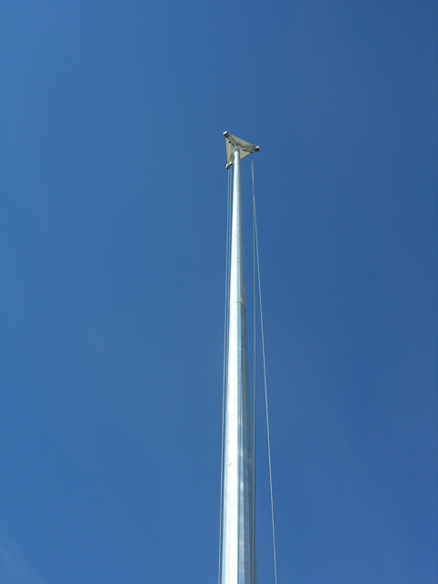
 The straight stepped columns in the Pa range produced by
CML s.r.l. are supports designed and built to sustain lamps or
projectors powered by an overhead cable line suspended at the eye-nut (G) prepared at height Hs (equal to 6.000 mm).
The column is realized with cylindrical tube elements with
decreasing diameter towards the upper part, appropriately fitted (stepped) and welded in sequence.
They are prepared for the assembly of:
– one column head lamp
– one series of fittings with pre-fixed inclination to gather from 1 to 4 lamps at the same time
– simple, double, triple arm brackets
– cross-members for mounting projectors.
– a power supply line with BT electric cable (max voltage 400 Vac).
The standard workings at the base of the column include the connection for the earth plant.
The eye-bolt (G) is welded at height Hs, to which the overhead cable line support rope is suspended: a hole (F) is made at the same height for passage of the lighting body power supply cable. At 100 mm from the eye-bolt, find the connection for the earth plant (T).
MATERIALS:
TUBE: tube realized in S 235 JR (UNI EN 10025) sheet steel
produced with ERW type-approved procedure.
WELDING:
circumferential performed with IIS certified automatic procedure.
TREATMENTS:
hot galvanisation in compliance with UNI EN 1461 of all components


COLUMNS FOR PHOTOVOLTAIC PANEL
 The straight stepped columns for support of the photovoltaic
panel kit produced by CML s.r.l. are supports designed and
built to sustain a self-powered system made up from a lamp
and one or more photovoltaic panels.
The column is realized with cylindrical tube elements with
decreasing diameter towards the upper part, appropriately fitted (stepped) and welded in sequence.
If needed, every column can be completed with it’s appropriate SF bracket, sold separatedly.
MATERIALS:
TUBE: tube realized in S 235 JR (UNI EN 10025) sheet steel produced with ERW type-approved procedure.
WELDING:
circumferential performed with IIS certified automatic procedure.
TREATMENTS:
hot galvanisation in compliance with UNI EN 1461 of all components.
Painting with thermosetting polyester powder cycle for outdoors.
STANDARDS:
dimensions and tolerance: UNI EN 40-2; Materials: UNI EN 40-5;
specification for characteristic loads: UNI EN 40-3-1; Verification by
calculation: UNI EN 40-3-3.


STRAIGHT CONICAL COLUMNS
 The straight conical columns in the PC range produced by CML
s.r.l. are supports designed and built to sustain one or more
lamps for lighting or projectors.
The column is obtained from trapezoidal sheet steel bent
longitudinally in successive phases in order to obtain the tapered section conformation. The longitudinal edges after bending are welded via an automatic process.
They are prepared for the assembly of:
– one column head lamp
– one series of fittings with pre-fixed inclination to gather from 1 to 4 lamp sat the same time
– simple, double, triple arm brackets
– cross-members for mounting projectors.
The standard workings at the base of the column include: n°
1 slot for terminal board, n° 1 connection for the earth plant,
n° 1 cable inlet slot. The details of these standard workings
performed at the base of the column are indicated separately in this catalogue on page 25.
MATERIALS:
MAST ROD: S 235 JR sheet steel (UNI EN 10025).
WELDING:
longitudinal performed with IIS certified automatic procedure.
TREATMENTS:
hot galvanisation in compliance with UNI EN ISO 1461 of all components
REFERENCE STANDARDS:
The columns are built in compliance with the UNI EN 40-5 Standard and the connected Standards: Dimensions and tolerance: UNI EN 40-2; Materials: UNI EN 40-5; specification for characteristic loads: UNI EN 40-3-1; Verification by calculation: UNI EN 40-3-3. The columns are “CE” marked in compliance with the EEC 89/106 Directive dated 21- 12-1988.
“CE” MARK:
Application of adhesive “CE” plate onto every column.
TECNICAL DOCUMENTATION:
Performance table of the column elaborated in compliance with UNI EN 40 3-3, “CE” declaration of conformity for every supply batch.


CURVED CONICAL COLUMNS (SINGLE ARM BRAKET)
 The curved conical columns in the PC range produced by CML s.r.l. are supports designed and built to sustain one lighting lamp.
The column is obtained from trapezoidal sheet steel bent longitudinally in successive phases in order to obtain the tapered section conformation. The longitudinal edges after bending are welded via an automatic process. Successively the column is cold bent on templates with suitable shape and size in order to obtain the curve envisioned by the model indicated.
They are prepared for mounting of one lamp per arm bracket.
The standard workings at the base of the column include: n° 1 slot for terminal board, n° 1 connection for the earth plant, n° 1 cable inlet slot. The details of these standard workings performed at the base of the column are indicated separately in this catalogue on page 25.
MATERIALS:
S 235 JR sheet steel (UNI EN 10025).
WELDING:
longitudinal performed with IIS certified automatic procedure.
TREATMENTS:
hot galvanisation in compliance with UNI EN 1461 of all components


CURVED CONICAL COLUMNS (DOUBLE ARM BRAKET)
 The symmetrical arm bracket is realized with the same construction method as the curved conical column (E) , which must be applied to the column itself.
The arm bracket is welded (S) to the column in the curved part (B) as schematised in the figure. In some models the double arm bracket can be realized disassembled, modular via couplings fastened using screws (V1 and V2). The standard workings at the base of the column include: n° 1 slot for terminal board, n° 1 connection for the earth plant, n° 1 cable inlet slot.
The details of these standard workings performed at the base of the column are indicated separately in this catalogue on page 25.
MATERIALS:
S 235 JR sheet steel (UNI EN 10025).
WELDING:
longitudinal and circumferential performed with IIS certified automatic procedure.
TREATMENTS:
galvanisation in compliance with UNI EN 1461 of all components


STRAIGHT OCTOGONAL COLUMNS
The straight octagonal columns in the PO range produced by CML s.r.l. are supports designed and built to sustain one or more lamps or projectors.
The column is obtained from trapezoidal sheet steel bent longitudinally in successive phases in order to obtain the pyramid section conformation with octagon base. The longitudinal edges after bending are welded via an automatic process.
They are prepared for the assembly of:
– one column head lamp
– one series of fittings with pre-fixed inclination to gather from 1 to 4 lamps at the same time
– single, double, triple arm brackets
– a series of brackets for projector assembly.
The standard workings at the base of the column include: n° 1 slot for terminal board, n° 1 connection for the earth plant, n° 1 cable inlet slot.
The details of these standard workings performed at the base of the column are indicated separately in this catalogue on page 25.
MATERIALS:
MAST ROD: S 235 JR sheet steel (UNI EN 10025): longitudinal welding with IIS certified welding procedure.
WELDING:
longitudinal performed with IIS certified automatic procedure.
TREATMENTS:
hot galvanisation in compliance with UNI EN 1461 of all components
REFERENCE STANDARDS:
the columns are built in compliance with the UNI EN 40-5 Standard and the connected Standards:
Dimensions and tolerance: UNI EN 40-2; Materials: UNI EN 40-3; specification for characteristic loads: UNI EN 40-3-1; Verification by calculation: UNI EN 40-3-3.
The columns are “CE” marked in compliance with the EEC 89/106 Directive dated 21-12-1988.
“CE” MARK:
Application of adhesive “CE” plate onto every column.
TECHNICAL DOCUMENTATION:
table of column performance elaborated in compliance with UNI EN 40-3-3, “CE” declaration of conformity for every supply batch


POLYGON COLUMNS FOR LARGE AREAS

The straight polygon columns in the GA range produced by
CML s.r.l. are supports designed and built to sustain one or
more lamps or projectors.
The column is obtained from trapezoidal sheet steel bent
longitudinally in successive phases in order to obtain the
pyramid section conformation with polygon base.
The longitudinal edges after bending are welded via an automatic process.The structure is realized with 2 tapered section tubular elements with polygonal sections (8 or 12 sides) that joins with forced coupling during installation on site. The column is prepared for assembly of projector-holder brackets.
The standard workings at the base of the polygon column
include: n° 1 slot for terminal board, n° 1 connection for the
earth plant, n° 1 cable inlet slot.
The details of these standard workings performed at the base of the column are indicated separately in this catalogue on page 25.
MATERIALS:
MAST RODS: realized in S 235 JR (UNI EN 10025) press-formed sheet steel and welding using IIS certified welding procedure
WELDING:
longitudinal performed with IIS certified automatic procedure.
TREATMENTS:
hot galvanisation in compliance with UNI EN 1461 of all components
TECHNICAL DOCUMENTATION:
instruction manual for installation of the column
.


TILTING COLUMNS
 The tilting columns in the PBA range produced by CML s.r.l. are supports designed and built to sustain one or more lamps or projectors with pre-established total minimum and maximum weights.
The column is obtained from trapezoidal sheet steel bent longitudinally in successive phases in order to obtain the pyramid section conformation with polygonal base.
The longitudinal edges after bending are welded via an automatic process.
The structure is realized with 1 tapered section tubular element with polygonal section (8 or 12 sides) onto which the end part of the column welded to the counter-weight element is hinged.
To carry out assembly or maintenance on the projectors and their accessories the support bracket can be lowered to the work level (Hs) at 1600-1700 mm from the ground.
Descent is obtained by making the upper part of the mast turn, which is hinged onto the lower mast and balanced by a counter-weight element called “shell”.
The activation of the descent and re-ascent can be performed manually via service ropes and a service pulley supplied as spare accessories.
The weight limits of the appliances mounted on the support brackets must be rigorously respecte.
When working the mobile part is fastened to the lower mast
With a bolt junction and safety lock.
The standard workings at the base of the tilting column include:
n° 1 slot for terminal board, n° 1 connection for the earth plant,
n° 1 cable inlet slot.
MATERIALS:
MASTS and SHELL: realized in S 235 JR or S 355 JR sheet steel (UNI EN 10025).
WELDING:
longitudinal performed with IIS certified automatic procedure.
SERVICE ROPE:
n° 1 in polyester
SERVICE PULLEY:
with safety hook, CE mark
TREATMENTS:
hot galvanisation in compliance with UNI EN 1461 of all components
LIFTING SYSTEM:
manual with control rope. Application of one or more pulleys to reduce (if necessary) the stress of the operator and take it back within the limits of Italian laws (max. stress not exceeding 30 kg).
TECHNICAL DOCUMENTATION:
instruction manuals for installation of the column, “CE” use and maintenance manual for the complete structure, application of monitory plates, plates for the parameters of use and identification plate


STANDARD WORKINGS (AT THE BASE OF THE COLUMNS)
 I pali prodotti da CML s.r.l. sono normalmente dotati delle lavorazioni di seguito descritte.
Asola per morsettiera: ricavata con taglio esente da sbavature sul perimetro del palo alla altezza (Hm) misurata dal fondo del palo.
Asola per ingresso cavi: ricavata con taglio esente da sbavature sul perimetro del palo alla altezza (Hc) misurata dal fondo del palo.
Morsetto di terra: attacco per il collegamento all’impianto di messa a terra del palo nella forma:
– a tasca (T1)
– con foro passante o filettato (T2)
– a bandiera con marchio CML (T3)
– a bandiera (T4)


SPECIAL WORKINGS (ACCESSORY SUPPLIES)
BELOW FIND A LIST OF A SERIES OF WORKINGS THAT CAN BE APPLIED TO STANDARD PRODUCTION

CURVED ARM BRANCKETS
 The arm bracket is realized with curved tube according to the radius envisioned: the lower part of the arm bracket is prepared for coupling with the support column.
The standard preparations are:
A1- forming of a cylinder (øA=70mm) with 3+3 threaded holes
for fastening onto the head of the column using STEI screws
A2- supply of double bracket for wall-fixing with sleeve and nut for fastening the arm bracket using STEI screws A3- application of a corner profile to attach to the support column to fix using steel band “e.g.: “band.it”)
The curved arm brackets (type A1) can be realized in version:
– single arm bracket (as per figure)
– double arm bracket (the two curved tracts can be positioned,
in plan, at 90° or at 180° to each other)
– triple arm bracket (the three curved tracts are positioned, in plan, at 120° to each other)
To favour handling, transport and galvanisation of the double and triple arm brackets, some elements may be disassembled.
MATERIALS:
TUBE: realized in S 235 JR (UNI EN 10025) sheet steel produced with ERW type-approved procedure.
TREATMENTS:
hot galvanisation in compliance with UNI EN 1461 of all components
REFERENCE STANDARDS:
the arm brackets are built in compliance with the UNI EN 40-5 Standard and the connected Standards:
Dimensions and tolerance: UNI EN 40-2; Materials: UNI EN 40-3; specification for characteristic loads: UNI EN 40-3-1; Verification by calculation: UNI EN 40-3-3


COLUMNS HEAD FITTINGS
 The column head fitting is realized with straight ERW tube welded to a cylinder with 2 threaded holes (or welded nuts) for for fastening onto the head of the column using TE screws.
The fittings can be realized in version:
– single fitting (figure “TS”)
– double fitting (the two arm brackets can be positioned, in
plan, at 90° or at 180°)
– triple fitting (the arm brackets are positioned, in plan, at 120° to each other, figure “TT”)
– quadruple fitting (the arm brackets are positioned, in plan, at 90° to each other)
To favour handling, transport and galvanisation of the double and triple arm brackets, one or more arm brackets may be disassembled.
MATERIALS:
TUBE: realized in S 235 JR (UNI EN 10025) sheet steel produced with ERW type-approved procedure.
TREATMENTS:
hot galvanisation in compliance with UNI EN 1461 of all components
REFERENCE STANDARDS:
The arm brackets are built in compliance with the UNI EN 40-5 Standard and the connected
Standards:
Dimensions and tolerance: UNI EN 40-2; Materials: UNI EN 40-3;
specification for characteristic loads: UNI EN 40-3-1; Verification by calculation: UNI EN 40-3-3


FITTINGS WITH WALL PLATE
 For the support of column head lamp in proximity of masonry walls or in reinforced concrete. CML s.r.l. has designed and realized arm brackets with a plate.
The arm bracket with plate is realized with ERW straight welded tube:
– A1- to a flat sheet steel bracket for wall fixing using screws and Rawplugs (or equivalent systems)
– A2- to a sheet steel bracket bent to 90° for wall fixing in correspondence with an edge using screws and Rawplugs (or equivalent systems)
MATERIALS:
TUBE: realized in S 235 JR (UNI EN 10025) sheet steel produced with ERW type-approved procedure. Welded with IIS certified welding procedure.
TREATMENTS:
hot galvanisation in compliance with UNI EN 1461 of all components


STRAIGHT COLUMN HEAD BRACKET
 The brackets are realized in sheet steel with slots (except for the circular bracket), press-formed and welded to a cylinder with 2 or 3 threaded holes (or welded nuts) for fastening onto the column head using TE screws.
To simplify the passage of the projectors to the circular bracket, the relative STFT60 or STFT30 accessory can be supplied on request. The square, hexagonal and circular brackets are connected, via welded tubular, to a central cylinder. The slots allow to install the projectors above or below the sides that make up the bracket. when the cables have been wired, the central cylinder is closed using a PVC cap with suitable diameter, supplied with the bracket.
MATERIALS:
BRACKET: realized in S 235 JR (UNI EN 10025) cold press-formed sheet steel.
TUBE: realized in S 235 JR (UNI EN 10025) sheet steel produced with ERW type-approved procedure.
TREATMENTS:
hot galvanisation in compliance with UNI EN 1461 of all components


SQUARE COLUMN HEAD BRACKET
 The brackets are realized in sheet steel with slots (except for the circular bracket), press-formed and welded to a cylinder with 2 or 3 threaded holes (or welded nuts) for fastening onto the column head using TE screws.
To simplify the passage of the projectors to the circular bracket, the relative STFT60 or STFT30 accessory can be supplied on request.
The square, hexagonal and circular brackets are connected, via welded tubular, to a central cylinder.
The slots allow to install the projectors above or below the sides that make up the bracket.
when the cables have been wired, the central cylinder is closed using a PVC cap with suitable diameter, supplied with the bracket.
MATERIALS:
BRACKET: realized in S 235 JR (UNI EN 10025) cold press-formed sheet steel.
TUBE: realized in S 235 JR (UNI EN 10025) sheet steel produced with ERW type-approved procedure.
TREATMENTS:
hot galvanisation in compliance with UNI EN 1461 of all components


HEXAGONAL COLUMN HEAD BRACKET
The brackets are realized in sheet steel with slots (except for the circular bracket), press-formed and welded to a cylinder with 2 or 3 threaded holes (or welded nuts) for fastening onto the column head using TE screws.
To simplify the passage of the projectors to the circular bracket, the relative STFT60 or STFT30 accessory can be supplied on request.
The square, hexagonal and circular brackets are connected, via welded tubular, to a central cylinder.
The slots allow to install the projectors above or below the sides that make up the bracket.
when the cables have been wired, the central cylinder is closed using a PVC cap with suitable diameter, supplied with the bracket.
MATERIALS:
BRACKET: realized in S 235 JR (UNI EN 10025) cold press-formed sheet steel.
TUBE: realized in S 235 JR (UNI EN 10025) sheet steel produced with ERW type-approved procedure.
TREATMENTS:
hot galvanisation in compliance with UNI EN 1461 of all components.


CIRCULAR COLUMN HEAD BRACKET
The brackets are realized in sheet steel with slots (except for the circular bracket), press-formed and welded to a cylinder with 2 or 3 threaded holes (or welded nuts) for fastening onto the column head using TE screws.
To simplify the passage of the projectors to the circular bracket, the relative STFT60 or STFT30 accessory can be supplied on request.
The square, hexagonal and circular brackets are connected, via welded tubular, to a central cylinder.
The slots allow to install the projectors above or below the sides that make up the bracket.
when the cables have been wired, the central cylinder is closed using a PVC cap with suitable diameter, supplied with the bracket.
MATERIALS:
BRACKET: realized in S 235 JR (UNI EN 10025) cold press-formed sheet steel.
TUBE: realized in S 235 JR (UNI EN 10025) sheet steel produced with ERW type-approved procedure.
TREATMENTS:
hot galvanisation in compliance with UNI EN 1461 of all components.


CYLINDRICAL COLUMNS
 The straight cylindrical columns in the PCL range produced by CML s.r.l. are supports designed and built to sustain one or more lamps or projectors. The column is realized with a cylindrical tubular element. They are prepared for the assembly of:
– one column head lamp (applying the reduction ø=60mm, H=120mm)
– the arm brackets with lateral attachment
The standard workings at the base of the column include: n°
1 slot for terminal board, n° 1 connection for the earth plant, n° 1 cable inlet slot. The details of these standard workings performed at the base of the column are indicated separately in this catalogue on page 25.
MATERIALS:
TUBE: realized in S 235 JR (UNI EN 10025) sheet steel produced with ERW type-approved procedure.
TREATMENTS:
hot galvanisation in compliance with UNI EN 1461 of all components
REFERENCE STANDARDS:
the columns are built in compliance with the UNI EN 40-5 Standard and the connected Standards:
Dimensions and tolerance: UNI EN 40-2; Materials: UNI EN 40-3; specification for characteristic loads: UNI EN 40-3-1; Verification by calculation: UNI EN 40-3-3.
The columns are “CE” marked in compliance with the EEC 89/106 Directive dated 21- 12-1988.
“CE” MARK:
Application of adhesive “CE” plate onto every column
TECHNICAL DOCUMENTATION:
Table of column performance elaborated in compliance with UNI EN 40-3-3, “CE” declaration of conformity for every supply batch.


COLUMNS FOR URBAN DESIGN
 The columns for urban design in the PCS range produced by CML s.r.l. are supports designed and built to sustain one arm bracket with lamp. The column is obtained from trapezoidal sheet steel bent longitudinally in successive phases in order to obtain the tapered section conformation.
The longitudinal edges after bending are welded via an automatic process.
The arm bracket is realized with a cylindrical tubular element fixed to the column via a mechanical joint that allows to direct the arm bracket with angle a = 0° ; 5° ; 10° ; 15°
The connection joint between the column and the arm bracket is covered with a spherical element, which can be supplied in various colours on request. Normally the connection joint is installed at a height Hb equal to 800 mm. The standard workings at the base of the column include: n° 1 slot for terminal board, n° 1 connection for the earth plant, n° 1 cable inlet slot. The details of these standard workings performed at the base of the column are indicated separately in this catalogue on page 25.
MATERIALS:
MAST ROD: S 235 JR sheet steel (UNI EN 10025): longitudinal welding with IIS certified welding procedure. ARM BRACKET: made from S 235 steel ERW tube (UNI EN 10025).
TREATMENTS:
hot galvanisation in compliance with UNI EN 1461 of all components
REFERENCE STANDARDS:
the columns are built in compliance with the UNI EN 40-5 Standard and the connected Standards:
Dimensions and tolerance: UNI EN 40-2; Materials: UNI EN 40-3; specification for characteristic loads: UNI EN 40-3-1; Verification by calculation: UNI EN 40-3-3. The columns are “CE” marked in compliance with the EEC 89/106
Directive dated 21-12-1988.
“CE” MARK:
Application of adhesive “CE” plate onto every column
TECHNICAL DOCUMENTATION:
Table of column performance elaborated in compliance with UNI EN 40-3-3, “CE” declaration of conformity for every supply batch.


ACCESSORIES
ARM BRACKETS S
 The arm brackets for urban design in the S range produced by CML s.r.l. are made from S 235 JR steel ERW tube (UNI EN10025) ø60×3 appropriately cold-shaped and can be applied to the entire range of standard columns.
The arm brackets can support one lighting lamp in “vertical” position (models S01, S1, S3, Su1 and Su3) or in “suspended” position (models S02, S2, S4, Su2 and Su4). The fixing systems of one or more arm brackets to the column are indicated in the following pages. The end of the arm bracket that must support the lighting lamp can have a male or female threaded fitting.

ARM BRACKET P
The arm brackets for urban design in the P range produced by CML s.r.l. are made from S 235 JR steel ERW tube (UNI EN10025) ø60×3 appropriately cold-shaped and can be applied to the entire range of standard columns. Every arm bracket can support one lighting lamp in the “suspended” position. The arm brackets in the simple, double or triple versions are supplied with a cylinder for insertion into the cavity of the top of the column: the other end can be equipped with a male or female threaded fitting.

FIXING SYSTEM FOR URBAN DESIGN ARM BRACKETS
The arm brackets for urban design produced by CML s.r.l. can be fixed to the standard range of columns via
especially designed fastening systems:
– shaped duct to be welded to the arm bracket (CNL range)
– modular coupling device (ACP range) made up from 2 rings for each column and 4 forks for each arm bracket
Every fastening system has a specific working on the arm bracket: the fastening system must be chosen
when the arm bracket is ordered.
The fixing systems allow to fix from 1 to 3 arm brackets onto one column.

MALE/FEMALE THREADED FITTINGS FOR URBAN DESIGN ARM BRACKETS
Male or female threaded sleeves with pitch suitable to the relative connection of the lighting lamp can be applied
to the entire range of arm brackets for urban design produced by CML s.r.l.

BASE FOR URBAN DESIGN COLUMNS
 The columns for urban design produced by CML s.r.l. can be equipped with a sheet steel base (CLB range) or a
cast iron base (BSM range) to improve the aesthetics of the column clamping zone. The bases are inserted onto the column until they rest on the floor.

STEPPED COLUMNS FOR TRAFFIC JUNCTION
 The stepped poles for traffic junction in the PRP range produced by CML s.r.l. are designed and built to support:
– traffic lights on roads
– signs for crossroads
– signs and advertising boards
– electric or electronic static equipment.
The column is realized with cylindrical tube elements with decreasing diameter towards the upper part, appropriately fitted (stepped) and welded in sequence.
The arm bracket is realized with ERW tube that is appropriately shaped and/or stepped.
The arm bracket is disassembled and is coupled into the seat at the top of the support column: definitive fastening is ensured with n°. 3+3 screws positioned radially.
The standard workings at the base of the column with door include: n° 1 slot for terminal board, n° 1 connection for the earth plant, n° 1 cable inlet slot.
The performance of the column must be previously checked by CML s.r.l. depending on use
MATERIALS:
MAST and ARM BRACKET: tube realized in S 235 JR (UNI EN 10025) sheet steel produced with ERW type
approved procedure.
WELDING:
circumferential performed with IIS certified automatic procedure.
TREATMENTS:
hot galvanisation in compliance with UNI EN 1461 of all components.


PEDESTRIAN TABLE
The pedestrian table provided by CML s.r.l. is composed of a 10mm thick anodized aluminum profile, a plex screen-printed in 3 colors on the inner surface of the two sides of the table. The tables can be supplied without any lighting, illuminated only internally by 3 lamps a 30 watt neon in the center of the box and with both internal and lower lighting for pedestrian crossing through 2 70 Watt high pressure sodium lamps (SAP) inserted entirely in the lower part of the box.
The installation on the appropriate portal supports designed and produced by CML can be carried out according to the modalities illustrated in the figures below. The luminous tables are supplied with collars for installation on the outreach (except for the fixed ones) and 12 mt. of electric cable.


OCTOGONAL COLUMNS FOR TRAFFIC JUNCTION
The octagonal columns for traffic junction in the POP range produced by CML s.r.l. are designed and built to support:
– traffic lights on roads
– signs for crossroads
– signs and advertising boards
– electric or electronic static equipment.
The column is obtained from trapezoidal sheet steel bent longitudinally in successive phases in order to obtain the pyramid section conformation with octagon base. The longitudinal edges after bending are welded via an automatic process.The arm bracket is realized with cylindrical tube elements with decreasing diameter, appropriately fitted (stepped) and welded in sequence. The arm bracket is disassembled and is coupled into the seat at the top of the support column: definitive fastening is ensured with n°. 4+4 screws positioned radially.
The standard workings at the base of the column with door include: n° 1 slot for terminal board, n° 1 connection for the earth plant, n° 1 cable inlet slot. The performance of the column must be previously checked by CML s.r.l. depending on use.
MATERIALS:
MAST ROD: realized in S 235 JR sheet steel (UNI EN 10025); ARM BRACKET: tube realized in sheet steel
S 235 JR (UNI EN 10025) produced with type-approved ERW procedure.
WELDING:
longitudinal and circumferential performed with IIS certified automatic procedure.
TREATMENTS:
hot galvanisation in compliance with UNI EN 1461 of all components


PEDESTRIAN TABLE
The pedestrian table provided by CML s.r.l. it is composed of a 10mm thick anodised aluminum profile, a 3-color screen-printed plex on the inner surface of the two sides of the table. The tables can be supplied without any lighting, illuminated only internally by 3 30-watt neon lamps in the center of the box and with both internal and lower lighting for pedestrian crossing through 2 high-pressure sodium lamps (SAP) of 70 Watts inserted entirely in the lower part of the box. The installation on the special portal supports designed and produced by CML can be carried out according to the methods illustrated in the figures below. The luminous tables are supplied with collars for installation on the outreach (with the exception of the fixed ones) and 12 meters of electric cable.
POLYGON COLUMNS FOR TRAFFIC JUNCTION

The polygon columns for traffic junction in the PPP range produced by CML s.r.l. are designed and built to support:
– traffic lights on roads
– signs for crossroads
– signs and advertising boards
– electric or electronic static equipment.
The column is obtained from trapezoidal sheet steel bent longitudinally in successive phases in order to obtain the pyramid section conformation with 12 sided polygon base. The longitudinal edges after bending are welded via an automatic process.
The arm bracket is disassembled and is fixed onto the top of the support column via the oblique flange and TDE nuts.The standard workings at the base of the column with door include: n° 1 slot for terminal board, n° 1 connection for the earth plant, n° 1 cable inlet slot. The performance of the column must be previously checked by CML s.r.l. depending on use.
MATERIALS:
MAST and ARM BRACKET: realized in S 235 JR or S 355 JR sheet steel (UNI EN 10025)
WELDING:
longitudinal performed with IIS certified automatic procedure.
TREATMENTS:
hot galvanisation in compliance with UNI EN 1461 of all components


PEDESTRIAN TABLE
The pedestrian table provided by CML s.r.l. it is composed of a 10mm thick anodised aluminum profile, a 3-color screen-printed plex on the inner surface of the two sides of the table. The tables can be supplied without any lighting, illuminated only internally by 3 30-watt neon lamps in the center of the box and with both internal and lower lighting for pedestrian crossing through 2 high-pressure sodium lamps (SAP) of 70 Watts inserted entirely in the lower part of the box. The installation on the special portal supports designed and produced by CML can be carried out according to the methods illustrated in the figures below. The luminous tables are supplied with collars for installation on the outreach (with the exception of the fixed ones) and 12 meters of electric cable.
FLAG POLE COLUMNS
 The flag pole columns in the PRA – PCA range produced by CML s.r.l. are used as flag or sign supports.
The column can be realized:
PRA range: with cylindrical tube elements with decreasing diameter towards the upper part, appropriately fitted (stepped) and welded in sequence.
PCA range: obtained from trapezoidal sheet steel bent longitudinally in successive phases in order to obtain the tapered section conformation. The longitudinal edges after bending are welded via an automatic process.
The column has two idle pulleys onto which a closed-ring cord must be installed, which is adequately taught to sustain and move the flag and PVC cap to close the end of the column.
The standard workings at the base of the column include the connection for the earth plant.
MATERIALS:
PRA- TUBE range: realized in S 235 JR sheet steel (UNI EN 10025) produced with ERW type-approved procedure.
PCA-MAST range: realized in S 235 JR sheet steel (UNI EN 10025)
WELDING:
circumferential (PRA columns) or longitudinal (PCA columns) performed using IIS certified automatic procedure.
TREATMENTS:
hot galvanisation in compliance with UNI EN 1461 of all components.


CONICAL COLUMNS FOR PENNANTS
 The conical columns for banners in the PPS range produced by CML s.r.l. are obtained from trapezoidal sheet steel bent longitudinally in successive phases in order to obtain the tapered section conformation. The longitudinal edges after bending are welded via an automatic process.
The column is used as support of the pennant-folder arm bracket.
The arm bracket is realized with a tubular rotation profile joined with two bearings.
The bearings are fixed to the top of the column using screws and allows the arm bracket to rotate freely on a horizontal plane.
An ornamental metal sphere is mounted on the top of the pole.
The banner is attached to the arm bracket via slotted seats made in the same and connected to the column with fabric rings: in the lower part the banner must have a ballast that holds it taught in a vertical direction.
When the banner is hit by wind it transmits the thrust to the rotating arm bracket that aligns itself with the direction of the wind itself. The standard workings at the base of the column include the connection for the earth plant.
MATERIALS:
TUBE: realized in S 235 JR sheet steel (UNI EN 10025).
WELDING:
longitudinal performed with IIS certified automatic procedure.
TREATMENTS:
hot galvanisation in compliance with UNI EN 1461 of all components


OCTAGONAL COLUMNS (FOR OVERHEAD LINES MT AND BT)
The column is obtained from trapezoidal sheet steel bent longitudinally in successive phases in order to obtain the pyramid section conformation with octagon base. The longitudinal edges after bending are welded via an automatic process.
The columns are prepared for the assembly of:
– support accessories or hook-up for isolators and bare cable lines
– support accessories or hook-up for MT and BT multi-polar cables.
The accessory workings of the column are:
– n° 1 transversal passing hole (øA=22mm) in proximity of the top of the column
– Welded baffle for covering (F2)
– Head fixing (F1)
– Identification marking
– Earth nut
– Bituminous protection band in the clamping zone only for this model of colums:9/A/10, 9/B/14, 10/A/10, 10/B/14, 10/L/10.
The workings are performed on columns as indicated in detail in the supply specifications drawn up by ENEL – Distribuzione SpA (RM) code DS 3010, edition June 2007.
MATERIALS:
COLUMN: S 235 JR or S 355 JR sheet steel (UNI EN 10025).
WELDING:
longitudinal performed with IIS certified automatic procedure.
TREATMENTS:
hot galvanisation in compliance with UNI EN 1461 of all components
REFERENCE STANDARDS:
The columns are built in compliance with ENEL-DS 3010 specifications. Dimensions and tolerance: indicated in the ENEL- DS 3010 specifications.
MARKING:
application of identification mark as indicated in the ENEL – DS 3010 specifications


POLYGON COLUMNS (FOR MT AND BT 2/3 SECTION)
The polygon columns for MT and BT overhead lines produced by CML s.r.l. are supports designed and built to sustain an electric overhead line realized in bare wires or overhead cable.
The column is obtained from 2 or 3 trapezoidal pieces of sheet steel bentlongitudinally in successive phases in order to obtain the pyramid section conformation with 16 sided polygon base. The longitudinal edges after bending are welded via an automatic process.
The 2 or 3 sections must be coupled with a thrust pre-established before being made to work.
The columns are prepared for the assembly of:
– support accessories or hook-up for isolators and bare cable lines
– support accessories or hook-up for MT and BT multi-polar cables.
The accessory workings of the column are:
– n° 1 transversal passing hole (øA=22mm) in proximity of the top of the column
– Baffle for covering with screw (F1)
– Head fixing
– Identification marking
– Earth nut
– Bituminous protection band in the clamping zone (to request)
The workings are performed on columns as indicated in detail in the supply specifications drawn up by ENEL Distribuzione SpA (RM) code DS 3012, edition May 2003.
MATERIALS:
COLUMN: S 355 JR sheet steel (UNI EN 10025): longitudinal welding with IIS certified welding procedure.
TREATMENTS:
hot galvanisation in compliance with UNI EN 1461 of all components
REFERENCE STANDARDS:
The columns are built in compliance with ENEL-DS 3012 specifications May-2003. Dimensions and tolerance: indicated in the ENEL- DS 3012 specifications
MARKING:
application of identification mark as indicated in the ENEL – DS 3012


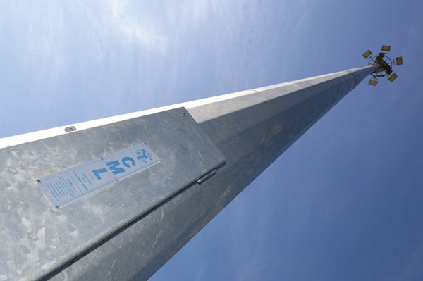
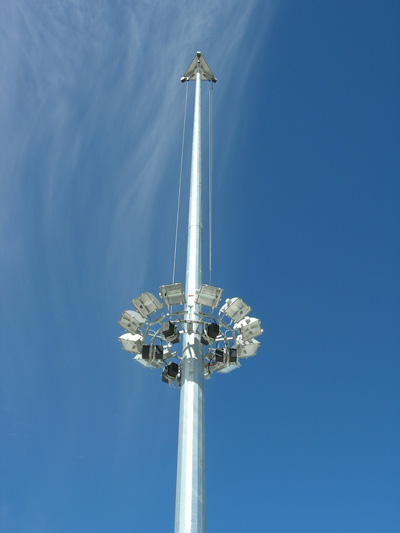
LIGHTING TOWERS WITH FIXED PLATFORM
 The support structure is realized with tubular pyramid section elements in press-formed sheet steel welded longitudinally: the masts must be mounted by means of forced coupling.
There is a platform on the top of the structure that delimits the work area and supports the projectors.
The fixed platform is accessed via a ladder fixed to the mast of the lighting tower. The steps can be the “ladder” type (protected by a metal cage) models “A” and “B” or the type “without protection” (equipped with type-approved fall-prevention system) model “C”. In order to allow the operator to rest during ascent or descent, the tower is equipped with one or two balconies positioned at a distance no greater than 10 metres between each other.
The rest balcony can be the “TR” type (as represented in the diagram) model “A” or the tipping type (contained inside the cage) model “B”.
In order to climb onto the “A” and “B” model lighting towers portable steps must be used that hitch onto the ladder fixed to the mast that ends at the height of about 1,800 mm from the ground.
The protection cage (where installed) starts at the height (Hs) of 2,500 mm from the ground floor. Unauthorised access to the ladder is prevented by mechanical means locked with a padlock.
The standard workings at the base of the tower include: n° 2 earth plant connections, n° 2 cable inlet slots.
MATERIALS:
MAST RODS: realized in S 355 JR (UNI EN 10025) press-formed sheet steel and welding using IIS certified welding procedure LADDER, PROTECTION CAGE AND ACCESSORIES: S 235 JR composite steel and/or cold-shaped sections
TREATMENTS:
hot galvanisation in compliance with UNI EN 1461 of all components
TECHNICAL DOCUMENTATION:
instruction manual for installation of the towers and accessories, “CE” use and maintenance manual of the complete structure, application of monitory plates and identification plates.


ACCESSORIES
REST BALCONY SUPPLIED WITH THE TP RANGE TOWERS version A
 The lighting towers with ladder and fixed platform in the TP range, version “A”, produced by CML s.r.l. must have rest balconies (as an alternative to the tilting footboard for resting in the RR range).
The balcony is realized with welded steel sections, walkway in metal mesh, access hatch with hinge, perimeter foot panel. The lateral protection railing is realized in welded steel sections. It is supplied complete with nuts and bolts for fixing the brackets welded onto the lighting tower mast. The Standards in force recommend the installation of a rest balcony at intervals no greater than 10 metres along the entire tract of the ladder.
MATERIALS:
S 235 JR composite steel and/or cold-shaped sections
TREATMENTS:
hot galvanisation in compliance with UNI EN 1461 of all components


TILTABLE REST PLATFORM
The lighting towers with ladder and fixed platform in the TP range, versions “B” and “C”, produced by CML s.r.l. must have tilting footboards for resting (as an alternative to the resting balcony in the TR range). The tiltable rest footboard is formed by two tread plates realized in bulb plate that can turn around a transversal axis joined to the support structure of the ladder. When the tread plates are raised they do not invade the transit zone and the operator can descend or ascend freely.
To rest, just climb to the upper step, lower the tread plates (as indicated in the axonometry) and use it to rest. In order to rest in safety the operator must be attached to the ladder by a safety belt. The Standards in force recommend the installation of the tiltable footboard at intervals no greater than 10 metres along the entire tract of the ladder.
MATERIALS:
S 235 JR composite steel and/or cold-shaped sections
TREATMENTS:
hot galvanisation in compliance with UNI EN 1461 of all components
TECHNICAL DOCUMENTATION:
instruction manual for installation of the tiltable footboard


FIXED PLATFORM
 The lighting towers with ladder and fixed platform in the TP range produced by CML s.r.l. must be equipped with the fixed platform to be installed on top of the tower. The service platform is made up from a base realized with walkway in metal mesh, access hatch with hinge, perimeter foot board, lateral protections in bolted steel sections.
The platform is supplied disassembled into its main components and complete with nuts and bolts for assembly of the structure.
Front and perimeter tubes are envisioned to fix the perimeters: as a fixing accessory the STFT50 bracket can be used.
MATERIALS:
S 235 JR composite steel and/or cold-shaped sections
TREATMENTS:
hot galvanisation in compliance with UNI EN 1461 of all components
TECHNICAL DOCUMENTATION:
instruction manual for installation of the platform


BRACKET FOR A PROJECTOR
 The fixing bracket is a useful multi-purpose accessory for fixing the projector to the peripheral tube of the protection railings of the fixed platform of the TP range lighting towers.
The bracket fastening system allows to direct the projector fixing base as required:
– on a horizontal plane – upwards or downwards, external or internal
– on a vertical plane – frontal
The projector fixed to the bracket can be turned to obtain the correct orientation.
The use of the bracket means that additional work does not have to be performed on the support tubes. Every supply includes the bracket and fixing accessories as indicated in the axonometric layouts.
ACCESSORIES SUPPLIED
– anti-ascent protection (n° 1 for every lighting tower) padlock excluded
– portable steps, with hook for attachment to the first step on the ladder (n° 1 for each site)


OBSTACLE SIGNS FOR FLYING TRAFFIC

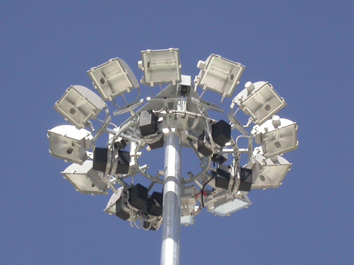
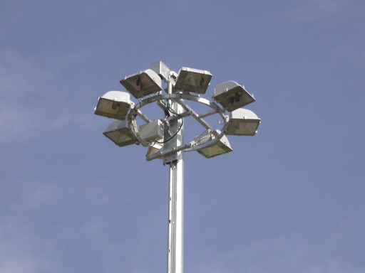
LIGHTING TOWERS WITH MOBILE CROWN
 Lighting towers with mobile crown in the TC range produced by CML s.r.l. are structures designed and built to sustain projectors and functioning accessories. The support structure is realized with tubular pyramid section elements in press-formed sheet steel welded longitudinally: the masts must be mounted by means of forced coupling.
The lifting head of the mobile luminaire ring is fixed onto the top of the structure.
The Lighting towers with mobile crown is a composite circular shaped structure with welded elements. The projectors can be positioned at 360°(A), at 180° (B) or with other positioning modes linked to the lighting engineering design.
The Lighting towers with mobile crown, in working position, is hitched to the lifting head by elastic stirrups. In order to perform maintenance on the projectors and their accessories the lighting towers with mobile crown to the work level (Hs) at 1600 – 1700 mm from the ground. A covering dome (C) with various diameters can be installed on the top of the lighting tower, above the lifting head.
The standard workings at the base of the tower include: n° 1 inspection door, n° 2 earth plant connections a, n° 2 slots for cable inlet and, on request, fall prevention braking system.
MATERIALS
MAST RODS:
realized in S 355 JR (UNI EN 10025) press-formed sheet steel and welding using IIS certified welding procedure
MOBILE LUMINAIRE RING:
S 235 JR composite steel and/or cold-shaped sections
LIFTING ROPES:
n° 3 made in AISI 304 stainless steel
COVERING DOME:
in S 235 JR sheet steel or in reinforced fibreglass with metal inserts
TREATMENTS:
hot galvanisation in compliance with UNI EN ISO 1461 of all components
ELECTRIC PLANT:
tower suitable to house n°1, 2 or 3 cables for the electric power supply of the projectors installed: every cable is multi-polar with 5 phases (3F+N+T) with suitable section for the total electric power, IMQ interlocked sockets and plugs, branch box and accessories with IP55 rating
LIFTING SYSTEM:
type-approved chain pulley tackle (wheeled or integrated), 400 Vac three phase power supply, control panel at 48 Vac, monitory plates and identification plate.
TECHNICAL DOCUMENTATION:
instruction manuals for installation of the tower and accessories, “CE” use andmaintenance manual for the complete structure, application of monitory plates and identification plate.


ACCESSORIES
MULTI-FUNCTION BRACKET FOR PROJECTORS
 The bracket is realized with steel sections and cold press-formed sheet steel. A series of appropriately sized slots are envisioned for connection of the projectors.
The projectors can be mounted in three positions at the top, at the bottom and in the front position. The bracket allows the assembly of several reflectors in different positions. The use of the bracket means that additional work does not have to be performed on the tubes of the mobile luminaire ring. Every supply includes the bracket and fixing accessories as indicated in the axonometric layout.
MATERIALS:
S 235JR composite steel sheet and/or cold-shaped sections
TREATMENTS:
hot galvanisation in compliance with UNI EN 1461 of all components


BRACKET FOR A PROJECTOR FOR MOBILE LUMINAIRE RING
The fixing bracket is a useful multi-purpose accessory for fixing a projector to the peripheral tube of the mobile luminaire ring supplied with the TC range lighting towers. The bracket fastening system allows to direct the projector fixing base as required:
– on a horizontal plane – upwards or downwards, external or internal
– on a vertical plane – frontal
The projector fixed to the bracket can be turned to obtain the correct orientation. The use of the bracket means that additional work does not have to be performed on the tubes of the mobile luminaire ring. Every supply includes the bracket and fixing accessories as indicated in the axonometric layouts.


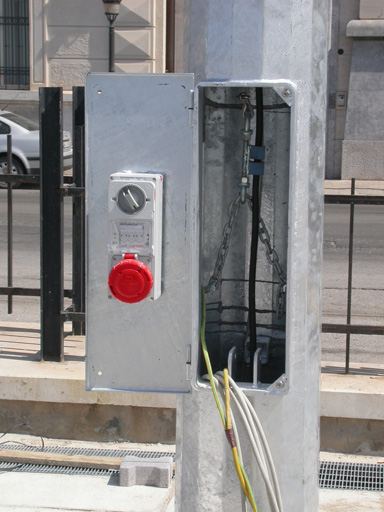
INSTALLATION KIT FOR AN ADDITIONAL ELECTRIC CABLE
The technical solutions adopted in the construction of the lighting towers with mobile crown and the lifting head of the TC range lighting tower allow to install 1, 2 or 3 cables for the electric power supply of the projectors installed: every cable is multi-polar with 5 phases (3F+N+T) with section suitable for the total electric power of the projectors installed.
The standard supply included in the supply of the lighting tower is 1 electric cable.
For the addition of one or more power supply cables, even after supply, an installation kit can be supplied that can be mounted with operations that can be performed on the top of the tower.
The kit includes: power supply cable with requested section, n° 5 pullets for the cable, n° 1 protection sump, n° 1 free safety socket, n° 1 free safety plug, n° 1 control board with interlocked socket to be installed inside the inspection hatch, n° 1 branch box with terminal board to be installed on the lighting towers with mobile crown, nuts and bolts and accessories


SUPPORT PLATES FOR THE ACCESSORIES
The support plates for the accessories to be installed on the lighting towers with mobile crown of the TC range lighting towers are realized in shaped and cold press-formed sheet steel. The PVE model is designed for a vertically fixed accessory. The accessory must be fixed to the plate using screws or rivets by previously drilling the plate according to necessity. The POR model is designed for a horizontally fixed accessory. Every supply includes the plate and fixing accessories as indicated in the axonometric layouts.


COVERING DOME
A covering dome can be installed on the top of the lighting tower. The various types of dome can be monobloc or in three modular elements. The dome is assembled with accessory brackets to be mounted on the lifting head. The CVTC2100,2800,4000 range domes are realized in stratified fibreglass and are normally available in the warehouse in RAL 7035 grey. Different colours can be produced on request. The fibreglass domes are realized in 3 pieces to be mounted with relevant assembly brackets..


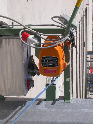
WHEELED LIFTING UNIT
 The chain pulley tackle is installed on a trolley with container for chain and idle wheels. The trolley can be easily moved into proximity of the lighting tower, appropriately hitched and put into operation. The pulley is powered by a three-phase extension with safety plug and socket, to be connected to the control board of the lighting tower: the pulley push button control panel allows the operator to work at a safe distance from the tower mast. The wheeled lifting unit is suitable for use on all TC range lighting towers produced by CML s.r.l. within the limits of its capacity
MATERIALS:
S 235JR composite steel sheet and/or cold-shaped sections
CHAIN PULLEY TACKLE:
“CE” Standard type-approved, 400 Vac power supply
PUSH-BUTTON CONTROL PANEL:
water-tight power supply 48 Vac
TECHNICAL DOCUMENTATION:
pulley tackle “CE” instruction and maintenance manual


INTEGRATED LIFTING UNIT
The chain pulley tackle is installed inside the base mast of the lighting tower. The pulley is powered by a three-phase extension with safety plug and socket, to be connected to the control board of the lighting tower: the pulley push button control panel allows the operator to work at a safe distance from the tower mast. The integrated lifting unit is suitable for use on the tower where it is installed.
MATERIALS:
S 235JR composite steel sheet and/or cold-shaped sections
TREATMENTS:
hot galvanisation in compliance with UNI EN 1461 of all components
CHAIN PULLEY TACKLE:
“CE” Standard type-approved, 400 Vac power supply
PUSH-BUTTON CONTROL PANEL:
water-tight power supply 48 Vac
TECHNICAL DOCUMENTATION:
pulley tackle “CE” instruction and maintenance manual


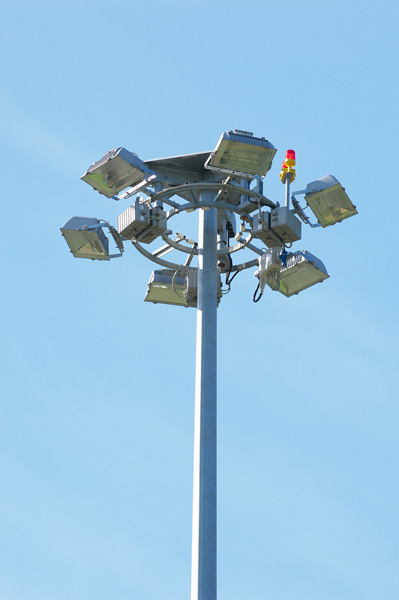
LIGHTING TOWERS WITH MOBILE TROLLEY
 The lighting towers with mobile trolley in the TM range produced by CML s.r.l. are structures designed and built to sustain projectors and functioning accessories.
The support structure is realized with tubular pyramid section elements in press-formed sheet steel welded longitudinally: the masts must be mounted by means of forced coupling. The lifting head of the mobile trolley is fixed onto the top of the structure. The mobile trolley is a composite structure with press-formed and welded elements.
It has 4 idle wheels to run along the vertical track fixed to the lighting tower mast.
A projector-holder luminaire ring is fixed to the mobile trolley or a frame formed with two appropriately fixed straight or shaped transversal bars.
The projectors can be positioned at 360° (A), at 180° (B), aligned (D) or with other positioning modes linked to the lighting engineering design. In the working position the mobile trolley is hitched to the lifting head of the tower. Movement of the mobile trolley can be manually activated or motorised. The mobile trolley has a fall-prevention safety system. A covering dome (C) with various diameters can be installed on the top of the lighting tower, above the lifting head.
The standard workings at the base of the tower include:
n° 1 inspection hatch, n° 2 connections for the earth plant, n° 2 cable inlet slots.
MATERIALS
MOBILE TROLLEY AND ACCESSORIES:
S 235 JR composite steel and/or cold-shaped sections
LIFTING ROPE:
n° 1 made of AISI 304 stainless steel
TREATMENTS:
n° 1 in acciaio inox AISI 304
TRATTAMENTI:
hot galvanisation in compliance with UNI EN 1461 of all components
ELECTRIC PLANT:
tower suitable to house n°1 cable for the electric power supply of the projectors installed: the multi-polar cable with 5 phases (3F+N+T) with suitable section for the total electric power, IMQ interlocked sockets and plugs, branch box and accessories with IP55 rating
LIFTING SYSTEM:
manually-activated pulley, type-approved chain pulley tackle. 400 Vac three phase power supply, control panel at 48 Vac
TECHNICAL DOCUMENTATION:
instruction manual for installation of the towers and accessories, “CE” use and maintenance manual of the complete structure, application of monitory plates and identification plates.


ACCESSORIES
SYSTEM WITH MOBILE TROLLEY
The mobile trolley of the TM range lighting tower runs on a vertical track by means of 4 idle wheels. The mobile trolley is lifted by the towing rope moved with the lifting units already described. Two support systems for the projectors can be applied onto the mobile trolley.
– circular luminaire ring for the radial position of the projectors (CMTM)
– horizontal cross-members for the aligned positioning of the projectors (TRTM)
The lifting system, system for hitching to the lifting head and fall-prevention safety device are installed on the mobile trolley.
The safety device is activated automatically if the rope should break.
The device is also activated automatically if the lifting rope is released too suddenly.
The projectors to be installed on the mobile luminaire ring can be mounted on supports or brackets that have been especially designed. The distribution of the projectors and their accessories (ignitors, branch boxes, etc…) must be performed in a way that the weights are distributed evenly on the surface.
When the position of the projectors is 360° it is recommended to position the projectors and accessories in a symmetrical way.
For the positioning of the projectors on horizontal crossmembers just make sure that the left and right side of every cross- ember is balanced. The total weight of the projectors, supports or brackets, accessories and any ballasts MUST NOT EXCEED THE USEFUL CAPACITY OF THE LIFTING UNIT
MATERIALS:
S 235JR composite steel sheet and/or cold-shaped sections
TREATMENTS:
hot galvanisation in compliance with UNI EN 1461 of all components


BRACKET FOR A PROJECTOR
The fixing bracket is a useful multi-purpose accessory for fixing a projector to the peripheral tube of the luminaire ring supplied with the TM range lighting towers. The bracket fastening system allows to direct the projector fixing base as required:
– on a horizontal plane – upwards or downwards, external or internal
– on a vertical plane – frontal
The projector fixed to the bracket can be turned to obtain the correct orientation. The use of the bracket means that additional work does not have to be performed on the tubes of the mobile luminaire ring. Every supply includes the bracket and fixing accessories as indicated in the axonometric layouts.


SUPPORT PLATE FOR ACCESSORIESI
The support plates for the accessories to be installed on the mobile luminaire ring of the TM range lighting towers are realized in shaped and cold press-formed sheet steel. The PVE model is designed for a vertically fixed accessory. The accessory must be fixed to the plate using screws or rivets previously drilling the plate according to necessity. The POR model is designed for a horizontally fixed accessory. A pair of POR models allows to fix the accessory by means of screws using the transversal slots as required. Every supply includes the plate and fixing accessories as indicated in the axonometric layouts..


BRACKET FOR A PROJECTOR FOR CROSS-MEMBERS
The STFT50 range fixing bracket is a useful multi-purpose accessory for fixing a projector to the TRTM range cross-member fixed to the mobile trolley of the TM range lighting towers. The bracket fastening system allows to direct the projector fixing base as required:
– on a horizontal plane – upwards or downwards, external or internal
– on a vertical plane – frontal
The projector fixed to the bracket can be turned to obtain the correct orientation. Use of the bracket means no additional work must be performed on the cross-members. Every supply includes the bracket and fixing accessories as indicated in the axonometric layouts.


COVERING DOME
A covering dome can be installed on the top of the lighting tower. The various types of dome can be monobloc or in three modular elements. The dome is assembled with accessory brackets to be mounted on the lifting head. The CVTM2100,2800 range domes are realized in stratified fibreglass and are normally available in the warehouse in RAL 7035 grey. Different colours can be produced on request. The fibreglass domes are realized in 3 pieces to be mounted with relevant assembly brackets.


MANUAL LIFTING UNIT
The device can be easily hitched to the base of the tower and made to function. The pulley is activated manually by the operator by means of a handle with adjustable arm. The frame of the device is dimensioned in a way to allow the operator to work at a safe distance from the tower mast. The manual lifting unit is suitable for use on all TM range lighting towers produced by CML s.r.l. within the limits of its capacity.
MATERIALS:
S 235JR composite steel sheet and/or cold-shaped sections
MANUAL PULLEY TACKLE:
with non-reversible worm screw device
TECHNICAL DOCUMENTATION:
pulley tackle “CE” instruction and maintenance manual


EXTERNAL ELECTRC LIFTING UNIT
The chain pulley tackle is installed on a frame with container for chain and idle wheels. The frame can be easily moved into proximity of the lighting tower, appropriately hitched and put into operation. The pulley is powered by a three-phase extension with safety plug and socket, to be connected to the control board of the lighting tower: the pulley push button control panel allows the operator to work at a safe distance from the tower mast. The external lifting unit is suitable for use on all lighting towers produced by CML s.r.l. within the limits of its capacity.
MATERIALS:
S 235JR composite steel sheet and/or cold-shaped sections
CHAIN PULLEY TACKLE:
“CE” Standard type-approved, 400 Vac power supply
PUSH-BUTTON CONTROL PANEL:
water-tight power supply 48 Vac
TECHNICAL DOCUMENTATION:
pulley tackle “CE” instruction and maintenance manual

